I said that a simple solution was to charge very carefully, at the right time, and for a limited amount of time. I shared a key tip: recharge immediately after use. I reminded him that lead acid batteries must not discharged and then left idle. Wayne appreciated the suggestions.
He asked about an alternate charger.
I asked if he had heard of the "Battery Tender" products. Possibly one of those chargers could be used. He didn't have one; he had heard the name.
Or if he had a smart charger already perhaps it would work. As I suspected, he did have one, for his car(s). I explained that that's what I did, mind you, I had a simple wiring configuration for my marine batteries.
We wondered about the wiring inside the booster pack... Could an automotive external charger be used on the booster pack terminals? I was concerned that a reverse flow may not be appropriate. Could we tap in somewhere else?
Removed the inverter to get a better look inside.
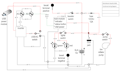
I made up a functional wiring diagram incorporating the battery source, the inverter with dual AC outlets, the USB output power port, the cigarette light adapter (CLA) power jack, the tire compressor, the big kill switch, the internal fuse, the external posts for jump-starting, the green and red marine lights, and the main module with status button, indicator, and input power charging port. Sent a diagram to Wayne but shared my caution. He agreed. It looked like recharging by the external posts would send power into the main module circuit board.
Wayne updated me that he had sourced a candidate battery in Barrie with a planned pick-up on Friday.
I decided to dive deeper into the main module printed circuit board.
Whoa! What happened to the rectifier diode?!
§
By popular request...
Here's the main diagram the I made showing the interconnections between all the components inside the case. Use at your risk...
Note wire colour and gauge is shown.


6 comments:
Hi ! Great info, thanks ! Experienced the same problem with the battery dying and opened the device... Now I'm wondering if it's worth investing in a replacement battery considering that, after reading your blog, the charger could be the issue and that there seems to be no real alternative...Thoughts ?
Hi Sébastien. I might have found a replacement battery so keep an eye on the blog. For an alternate charger wall-pack, I would recommend a Battery Tender smart charger.
I too am looking for a battery for one of these. If I can't find one I plan on using some UPS batteries in parallel.
How about showing us your wiring diagram?
Would that be possible?
A wiring diagram would be helpful
Si por favor el diagrama de cableado
Post a Comment