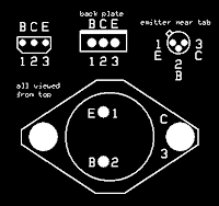
I sorted an issue with the switching transistors. Initially, I mistakenly used the same pin position assignments for the 2N2222 and TIP31C pieces.
I learned that you need to go back to the schematic and ensure the pins of the physical part correspond to the schematic.
After testing a simple 555 schematic from Math Heijen, I successfully debugged my soldered 556 board layout. Carefully comparing the schematic and board layout, I found the error. It was caused by a fault back in mid-January, when I first considered the board layout and I changed from the stock diode object. With my "custom" diode part, I flipped the polarity. I edited the part polarity in ExpressPCB and repaired the board.
Below, is the full, correct board layout I used.
The board has left and right sections meaning the left R1 potentiometer controls the power output to heaters H1 and H2 and which is reflected in diode D5. Close examination will reveal the correct orientation of the signal diodes. It's a little messy around the TO-18 transistors but the traces drawn indicate where the long legs were attached (when possible). The offsetting (again) of B1 and F1 show the power source is outboard and the fuse is inside the CLA plug.
Cut the long 4-40 bolts for the heat sinks (first time doing that with the GB wire stripping tool). The PCB was (nearly) done and working.
The heavy gauge red and black wires (in the photo) at the upper corners of the PCB are for the heater networks of course. The yellow, purple, and black wires at the bottom corners are for the pots. In my case, the black wires are for the middle pins. You can clearly see one of the indicator diodes; the other is cropped out. The black wire going from the middle of the board straight up in the negative 12 volt power input. I used the red lead at the bottom-right as a temporary feed into the PCB.
With the controller working, I was able to test with the Schottky diode. It was fine, of course. But it will require some special effort: the pins are a bigger girth so I'll have to drill the PCB...
I'm ready for the next phase. Yeh, I can cut the long leads off the bottom of the PCB. I'll attach the case parts now, the pots, the RCA plugs, the power switch, and power feed. Saw a neat trick of gluing stand-offs to the project box so I'll see if I can pull that off...
§
Next: finished dew controller.


No comments:
Post a Comment